
Overview
In this section we will look at a number of common sensors used to measure flow and depth and we will examine the principles behind their operation.
Objective
- Understand the principles applying to the measurement of flow.
- Be aware of some of the different transducers used to measure flow and depth: their principles of operation and their pros and cons.
Study Time: 4.0 hours

This section will explain the different types of fluid flow, Laminar and Turbulent flow, the equations required when flow occurs in pipes and finally the principles behind the flow transducers. We will then go on to look at some common sensors used for measuring depth, and will discuss some of the pros and cons of each transducer type.
Types of Flow
Incompressible fluids can undergo two types of flow when constrained in a closed pipe or tube; these are turbulent flow and viscous or laminar flow. In turbulent flow the fluid particles move in a disorderly manner and occupy different relative positions in successive cross-sections; in laminar flow the fluid particles move in an orderly manner and retain the same relative positions in relative cross-sections. This is shown in the diagram below:
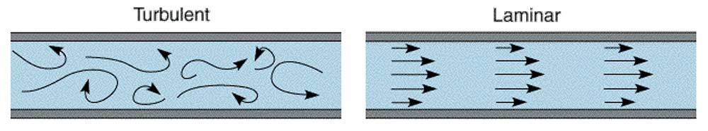
A way to determine the differences between these types of flow is the Reynolds number of the flow. If the Re is less than 2300 then it is laminar flow if it is above or equal to 2300 it is turbulent.
The equation for determining the Reynolds number is shown below:
Where Re is the Reynolds number, v is the speed of flow, r is the radius of pipe, ρ is the density of fluid and μ is the viscosity of the fluid.
Task 1
A fluid has a viscosity of 0.97 x 10_3 kg/m.s and density 1.2 x 10³ kg/m3. It is flowing through a pipe of internal diameter 10cm at a velocity of 1.5m/s. What is the Reynolds number?
R = 1.5 x 0.1 x 1.2 x 103/0.97 x 10-3 = 1.86 x 10⁵
Bernoulli Principle
Bernoulli's Theorem applies to frictionless flow (i.e. where friction can be assumed to be negligible). It states that the total energy of each particle of a body of fluid is the same, given that no energy enters or leaves the system at any point.
This equation only applies to slow flow, less than Mach 0.2.

A fluid can possess three forms of energy, potential, pressure and kinetic energy.
Potential energy describes the elevation of the fluid above some datum level. If a weight of liquid W (W = liquid density x gravitational force = ρg) is at a height of h metres above datum:
it possess potential energy = W.h = ρgh
potential energy per unit weight = h
Pressure energy describes the ability of a continuous stream of fluid under pressure to do work. If the area of a cross-section of the fluid is A (m2) and the pressure at the cross-section is P then the force acting due to pressure at the cross-section is P.A. For a weight of fluid W passing the cross-section, the volume passing the cross-section is W/w where w is the specific weight of the fluid.
The distance moved by the fluid: W/wA
Work done by fluid = force x distance
pressure energy per unit weight = P/w = P/(ρ.g) where ρ is the density.
Kinetic energy is the energy possessed by the fluid by virtue of its velocity.
If a weight of fluid W has a velocity v: Kinetic energy =
kinetic energy per unit weight = v2/2g
The total energy of the fluid is the sum of these three forms:
Total energy per unit weight = H = h + P/w + v2/2g
H is often referred to as "the total head". Bernoulli's Theorem leads directly to Bernoulli's Equation which combines the three types of energy within the fluid flow to determine the total energy of the fluid.
Where P is pressure in Pascals, ρ is density in kg/m3, v is speed of flow and z is the vertical displacement. The equation states that all flow is conserved in pipes provided that friction is ignored.
As well as the need to quantify the flow of liquids there is an obvious engineering need to quantify the flow of gases. A gas differs from a liquid in that it is readily compressed to a higher density or expanded to a lower. The theories, relating to gases undergoing significant compression or expansion in this manner is markedly different to those applying to liquids. However slow-moving gas demonstrates negligible changes in density; that is the flow of slow-moving gas follows the same laws as those for a liquid.
It is obviously important to define "slow-moving".
As a general rule, the laws of liquid flow can be applied to a gas if the Mach number, M, everywhere within the gas is less than 0.2. The Mach number is the ratio of the speed of the gas flow to the speed of sound within the gas. The speed of sound within the gas is a function of the gas density, pressure and temperature:
where γ = Cp/Cv is a constant equal to the ratio of the specific heat of the gas at constant pressure and constant volume,
P is the gas pressure in N/m2 (or pascals, Pa), and,
γ is the gas density in kg/m.
γ is found from tables. Air for example has a γ value of 1.4.
Flow Quantification
Bernoulli's equation quantifies flow in a pipe where there are no losses. In practical situations losses occur due to shocks and friction at the pipe walls.
Shock losses occur:
- where there is a sharp entry from a reservoir into a pipe, or,
- where there is a sharp exit from a pipe into a reservoir, or,
- where there is a sudden enlargement or reduction in the pipe diameter.
If it can be assumed (as it will be here) that all entries, exits, enlargements and reductions are smooth and gradual then the only significant loss is due to friction.
Various formulae exist to quantify frictional losses but probably the most important is the Darcy Formula:
Loss of head due to friction = 4flv2/2gd
where:
f is the coefficient of friction (dimensionless),
l is the pipe length (m),
v is the fluid velocity (m/s),
d is the pipe diameter (m), and,
g is gravitational acceleration = 9.81 m/s2
Thus Bernoulli's formula can be extended to include flows subject to frictional losses:
Total head, H = h + P/w + v2/2g + 4flv2 /2gd
Flow Transducers
Venturi Tubes
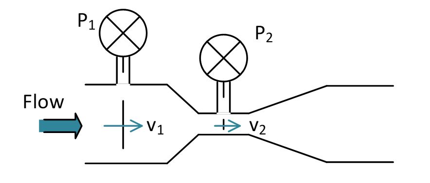
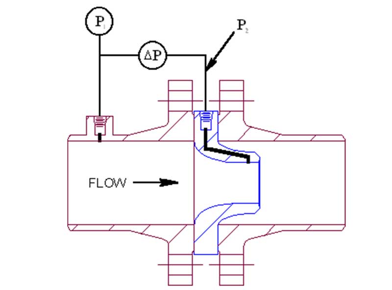
The Venturi meter consists of a short converging conical tube leading to a cylindrical portion called the throat which is followed by a diverging section. The entrance and exit diameter is the same as the pipeline into which it is inserted. For continuity of flow the velocity v1 at the entry section will be less than the velocity v2 at the throat section, since A1v1=A2v2 and A1 is greater than A2.
The kinetic energy in the throat will be greater than at the entrance, and since by Bernoulli the energy at both sections is the same, the pressure energy in the throat will be less than at the entrance. There is thus a pressure difference between the two sections, which is dependent on flow.
The angle of the convergent cone is usually 21 degrees, the length of the throat equal to the throat diameter and the angle of the divergent cone equal to 5.5 degrees, which minimises losses.
Now flow:
A = cross sectional area of tube; P = pressure; ρ = density and C is a value obtained by calibration. As A, C, and ρ are all constants then we can rewrite this as:
Where ΔP is the change in pressure (N/m2), K is a constant and Q is the volumetric rate of flow (m3/s). Hence the flow can be calculated and used for instrumentation purposes.
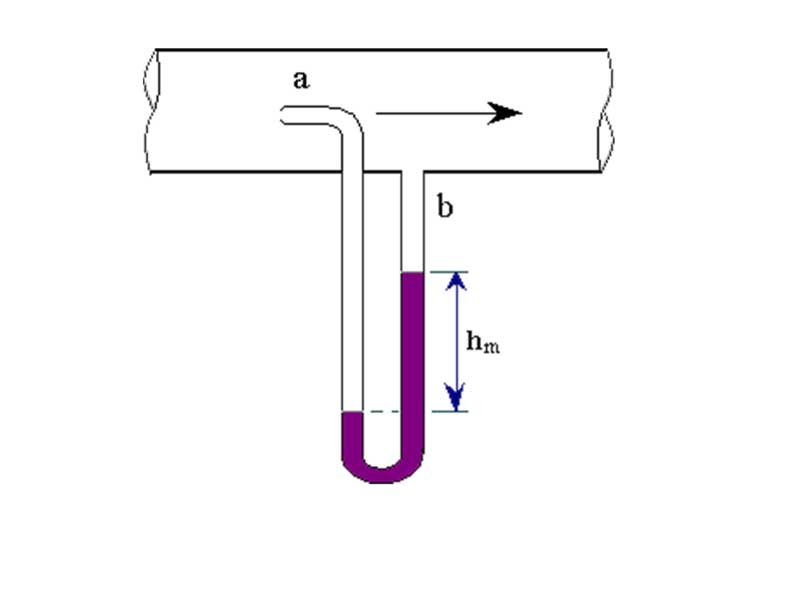
Differential Manometer
A differential manometer can be connected to tapping points in the entrance and throat of the Venturi; the manometer reading gives ΔP from which Q is obtained.
ΔP can also be measured by means of a differential pressure (DP) cell.
It should be noted that the output from this system is related to the flow squared and therefore requires linearisation.
Link
Find out more about DP flowmeters at: https://www.omega.com/literature/transactions/volume4/T9904-07-DIFF.html#diff_1
Task 2
-
A venturi flow meter with a head loss of 10% is specified as having a flow range of 0.02 to 0.2 m3/s and a measured pressure difference at maximum flow of 120 kPa. Water enters the meter at a pressure of 200kPa.
-
If water is flowing at 0.1 m3/s, what is the measured pressure difference?
-
If the measured pressure difference is 90 kPa, what is the flow rate of the water?
-
What is the head loss across the transducer at a flow rate of 0.2 m3/s.
-
-
There are a number of other differential pressure, restriction type, flow meters. Can you name and describe at least three?
-
-
From , at 0.2m3/s, ΔP = 120kPa, so K = 18.26 x 10⁻³
Therefore at 0.1m3/s, from the same equation, ΔP = 30kPa
-
If ΔP = 90kPa, Q = 0.173m3/s
-
10% of 120kPa = 12kPa
-
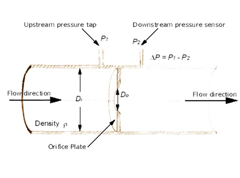
- Examples of flow meters
Orifice Plate
Pitot Tube
Flow Nozzle
-
Turbine Flow Meter
In this device a cylindrical port has a closely-fitted freely spinning vane assembly located within it. Any movement of fluid through the meter causes the vanes to rotate with the volume swept in one complete rotation being accurately metered.
Vane rotation is converted to a pulsing electronic signal by optical or magnetic means.
In this device, the faster the optical detector detects lights the faster the rotating turbine is moving and the faster the flow.

The disadvantage of using a propeller for accurate measurements (for example for gauging oil and gas production for tax and pipe rental purposes) is that the propeller is a precision item and therefore expensive. This is also an intrusive measurement method, requiring insertion in the fluid, which may be impractical and possibly also an extreme environment for the sensor (particularly since it has moving parts which might be unreliable in the environment).
Link
Find out more about turbine propeller flowmeters at: http://www.omega.com/literature/transactions/volume4/T9904-08-MECH.html#mech_1
Ultrasonic
Methods using ultrasound have the advantage that where the flow to be measured is a pipe of a suitable material which allows a good impedance match to be made between the pipe and the transducer, the method is non-invasive. Various such systems exist, but an important class employs the Doppler Principle to gauge the flow.
The transducer axis is aligned partially along the direction of flow so that it is the same or the opposite sense.
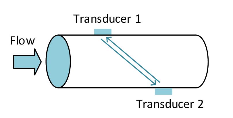
A piezoelectric transmitter element is continuously excited by a sinusoidal signal, of frequency f Hz, which causes sound of this frequency to propagate into the flow. Some of the sound energy is reflected by particles or bubbles in the fluid with a Doppler shift +Δf, depending on whether the ultrasound is in the direction of the flow or against it. The magnitude of the shift is directly proportional to the flow rate (making allowance for the angular relationship between the transducer ad flow axes). The reflected signal is received by a piezoelectric receiver element and compared with the transmitted signal so that the Doppler shift can be measured and the flow deduced.
Link
Find out more about ultrasonic flowmeters at: http://www.omega.com/literature/transactions/volume4/T9904-09-ELEC.html#elec_4
Electromagnetic Flow Meter
This method only works for electrically-conductive fluids as it depends on Faraday's Law of Electromagnetic Induction. A magnetic field is created at right angles to the flow, with a set of electrodes positioned at right angles to both the flow and field.
The fluid constitutes the flux cutting conductor with an electromagnetic force produced at the electrodes proportional to the flux-cutting rate, i.e. the flow rate.

Link
Find out more about electromagnetic flowmeters at: http://www.omega.com/literature/transactions/volume4/T9904-09-ELEC.html#elec_2
Positive Displacement/Volumetric Flow meter
Positive displacement flow meters are the most common type used for measuring domestic gas and water consumption. All positive displacement flowmeters work by using mechanical divisions to displace discrete volumes of fluid successively, and are low friction, low maintenance, long-life devices. They can be used with high viscosity fluids, but do impose a small permanent pressure loss on the flowing fluid.

Depth Measurement
Ultrasound
The depth of a liquid or liquid-like substance (such as grain, sugar, for example) can be detected by an ultrasound transducer located at the base or top of the tank. The transducer is pulsed and the pressure wave so generated propagates towards the surface where a proportion of the energy is reflected.
On arrival back at the transducer the pressure wave produces an electrical signal due to the inverse piezoelectric effect; this signal can be processed into a pulse which indicates the arrival time of the reflected wave. The total propagation delay describes the propagation path length if the speed of sound in the medium is known:
td = 2d/v
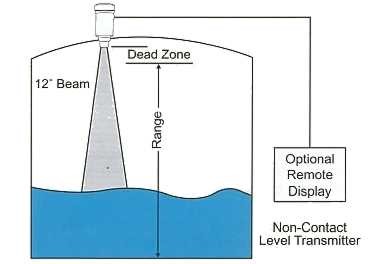
It should be noted with this method that multiple reflections can cause erroneous results. Retransmission should not occur until all reverberations from the previous transmission have decayed to an insignificant level.
The higher the required resolution, the higher the frequency of sound that is required. The attenuation of sound increases with frequency, and also depends on the medium. The speed of sound is also temperature dependent.
The main advantage of this method is that it does not require contact with the fluid.
Capacitive Methods
This method makes use of two parallel rod transducers (or one rod and the side of a conductive tank) which are inserted into the fluid container.
The rods constitute the electrodes of a capacitor while the fluid acts as the capacitor dielectric. Thus the capacitance of the transducer describes the fluid level.
An advantage of this method is that it can easily be used to provide an ac signal (by tuning an oscillator for example).

Hall Effect
In 1879 Edward Hall discovered that when a current carrying conductor was placed in a perpendicular magnetic field, a voltage was induced across it at right angles to both the current and the magnetic field. Semiconductors exhibit this effect most dramatically and it is caused because the current carrying particles (usually electrons) flowing through the conductor are deflected by the magnetic flux of the magnet.

If a powerful magnet is inserted within a float, the Hall Effect can be used to trigger Hall Effect latching sensors positioned alongside a tank, to detect when the float reaches a specific level. This avoids the need to place the sensor within the tank, so hot or corrosive fluid levels can be safely measured this way.
Hall Effect sensors are also used regularly as position sensors, proximity sensors, speed sensors etc.
Summary
In this section we have looked at some common methods of measuring flow and depth, and considered some of the pros and cons of each sensor/instrument.
References
Morris, Alan S. (2001) Measurement and Instrumentation Principles 3rd edition, Oxford: Butterworth-Heinemann (ISBN 0-7506-5081-8)
National Instruments Website <http://www.ni.com/tutorials/> accessed [21/06/17]
Omega (n.d.) Differential Pressure Flow Meters [online]. Available from <http://www.omega.com/literature/transactions/volume4/T9904-07-DIFF.html#diff_1> accessed [21/06/17]
Sensorland Website <http://www.sensorland.com/> accessed [21/06/17].#