Overview
In this section you will learn about some of the most common transducers used to measure displacement, speed and temperature. You will also see some of the signal conditioning circuits used with these sensors to improve their performance.
Objective
- To understand the working principles behind some of the most common displacement, speed and temperature sensors.
- To recognize the need for signal conditioning and to be able to design or specify suitable signal conditioning circuits for common displacement, speed and temperature sensors.
Study Time: 6.0 hours
In addition, we will also look at the working principles of Potentiometers and Linear Variable Differential Transformers, used for measuring displacement. We will then move on to Tachogenerators and Shaft Encoders which are used for measuring angular speed. Temperature sensors are then considered, including Thermistors, Thermocouples and Integrated circuit sensors, with the signal conditioning circuits required to meet accuracy, linearity and range specifications examined.
Introduction
Transducers are essential elements within instrumentation systems as they sense the physical parameters of interest and produce electrical signals which are then available for processing and analysis.
The range of parameters encountered in the field of instrumentation is very wide. This course is restricted to a brief discussion of the principles for the transduction of position, temperature, force, pressure, acceleration and flow. Various different transduction principles may exist for a given parameter.
In general, in the interests of brevity, only one or two of the more important methods are discussed. We will start by looking at some sensors for displacement, speed (and velocity – the equivalent vector, remembering that speed is a scalar property) and force.
Displacement Transducers
Rotary (Angular) Position and Speed
Shaft Encoder
Shaft encoders are examples of direct digital transducers, being, in effect, mechanical angular position to digital converters. There is obviously a great need for such devices which allow the positions of shafts and other rotational components to be registered digitally. In essence, a coded wheel is attached to a shaft. The code wheel is either equipped with transparent and opaque segments or absorbent and reflective segments. Light transmitted through or reflected from the wheel is detected by photosensitive devices, the outputs of which are conditioned to provide logical 1’s or 0’s.
Absolute positional information may be obtained if the position of the wheel at any point has a unique code associated with it, the number of bits in the code determining the resolution of the positional indication. This is possible if the wheel is split into a number of concentric annular rings, (a ring for each bit).
Figure 1 Shaft Encoder
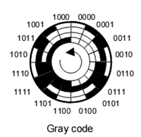
The figure shows a 4-bit Gray-coded disc. Gray code is particularly suitable for positional encoding because it is so-called one-change code – only one bit changes between adjacent entries in the table. Thus the position of a Gray coded shaft, as registered by an optical sensing system, can only have a 1-bit uncertainty. The 4-bit wheel only has a resolution of a sixteenth of a revolution; this is obviously very poor and a practical encoder would have a higher number of coded rings and bits
Task 1
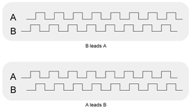
How could a shaft encoder give information about direction and speed of rotation?
Incremental rotary encoders have two light sources and two photodetectors, which produce waveforms which are 90˚ out of phase (in quadrature). These signals are digitally decoded to produce a count up pulse or a count down pulse, thus rotational direction can be established. Speed can be determined by the frequency of the pulses

Find out more about encoders at http://www.smallformfactors.com/articles/id/?3039
Tachogenerators
Tachogenerators are basically AC (without a commuator) or DC (with a commuator) generators based on Faraday’s electromagnatic induction principle. Basically, as an electric conductor (e.g. copper wire) cuts the flux lines of a magnetic field, an electric current is induced in the wire, which produces an electromotive force (emf). The size of the voltage is proportional to the speed at which it cuts through the flux. If the wire is wound as a coil on an armature, then spun within the magnetic field, the no load voltage produced is directly proportional to the speed at which the coil is spinning, so can be used to accurately measure the rotational speed of the armature shaft.
where E = EMF (V), N = Number of turns of wire, Φ = magnetic flux (Webers)
With DC tachogenerators the direction of rotation can also be determined by the polarity of the voltage.
Displacement Transducers
Linear Position
Linear Variable Differential Transformer (LVDT)
Electrical analogue transducers which detect linear position or displacement may in essence be resistive, capacitive or inductive. Inductive types have the advantage of having no rubbing contact between component parts, so avoiding wear. The most important and popular of these is probably the linear variable differential transformer (LVDT), which is somewhat like a centre tapped transformer with a moveable core. In the centralised (null) position the output from the transformer is balanced and the demodulator produces a null output. An increasing movement of the core one way or the other destroys the symmetry of the magnetic circuit and gives a net positive or negative output, depending on the sense of the deflection. For small deflections the output/deflection relationship is linear, so the displacement of the core can be determined from the phase and amplitude of the output.
Find out more about LVDTs at the Sensorland website.
Potentiometer
A potentiometer is a variable electrical resistance. A length of resistance material has a voltage applied over its ends. A slider moves along it (either linear or rotary) and picks off the voltage at its position or angle. The tracks may be made from carbon, resistance wire or piezo resistive material. The latter is the best because it gives a good analogue output. The wire wound type produces small step changes in the output depending on how fine the wire is and how closely it is coiled on the track.
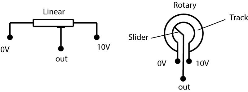
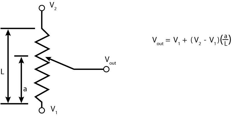
Figure 4 Potentiometer
Task 2
Design a circuit using a potentiometer to give a variable output without significantly changing the current drawn from a supply.
Temperature Transducers
Semiconductor Temperature Sensors
Linear integrated circuits have been developed which deliver well-defined current or voltage changes with temperature. One of the most useful and widely-applied of these is the AD590, which is a two-terminal integrated-circuit temperature transducer employing current mirror technology to produce an output current proportional to absolute temperature. A range of these, having general purpose (inexpensive) to precision (expensive) specifications is available.
For supply voltage between +4V and +30V the device acts as a high impedance (>10MΩ) constant current regulator passing 1µA/K. Laser trimming is employed at manufacture to calibrate the device for a 298.2µA output at 298.2K (+25 °C).
Fig 5a illustrates the simplest possible means of obtaining a temperature measurement using the AD590. Its operation is self evident.
Fig 5b shows a minimum circuit for obtaining a temperature dependant voltage from an AD590. The supply voltage to the device sets up the signal current and the load resistor, trimmed to l 0k, provides the current-to-voltage conversion of l0mV/μA.
For an output referenced to 0V it is convenient to use an op amp connected as a current-to-voltage converter (or "transresistance" amplifier), fig 5c. The offset current, adjusted by setting Ros, can be removed from the summing junction to a negative voltage supply rail. The o/p voltage magnitude is set by choice of the transresistance gain R.
Fig 5d is a simple circuit for measuring differential temperature. One amplifier provides the negative bias for current I1 while the other provides current to voltage conversion for the difference current (I2-I1).
In all applications care should be taken to adequately couple the AD590 to the component or environment under investigation. In critical applications the bias voltage should be supplied from stable reference sources and op amps, where used, should be low bias current types with low voltage drift qualities.
The AD590 is particularly useful in remote sensing applications. The device is insensitive to voltage drops over long lines due to its high impedance current output. Any well-insulated twisted pair is sufficient for operation up to a hundred metres or more from the receiving circuitry.
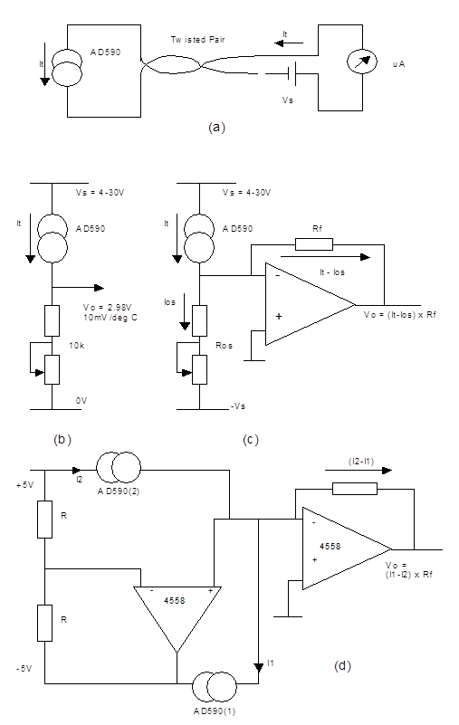
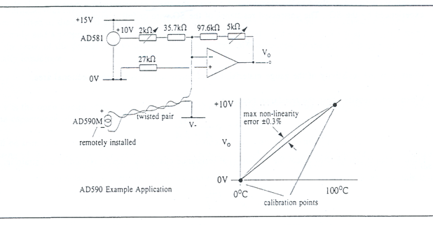 Figure 6 Remote acquisition of temperature data using AD590
Figure 6 illustrates the application of an AD590 in the remote acquisition and conditioning of a temperature signal in preparation for A to D conversion. In this application an accuracy of ±0.3% has to be achieved which requires the use of one of the high specification AD590’s. The trim resistors allow the trimmable errors to be removed as part of a calibration procedure.
Temperature Transducers
Thermocouple
The principle on which the thermocouple is based is the Seebeck Effect – the appearance of a voltage across the junctions of dissimilar metals at different temperatures – the reverse of this effect is known as the Peltier Effect which is the change of temperature resulting from the flow of current through the junctions of dissimilar metals. The reading of a thermocouple will inevitably lead to a flow of current due to the Seebeck voltage into the measurement circuit. This flow causes non-linearities in the calibration of the thermocouples due to the Peltier effect. Every connection of different metals which is made within the thermocouple loop – for measuring devices, extension leads etc – will contribute to the Seebeck voltage. Because of this, care must be taken to ensure that the wiring scheme for the transducer is compatible with the thermocouple junctions in use. To connect far away sensors, compensating cables are sometimes used, which are cheaper versions of similar materials forming the thermocouple (to reduce the number of dissimilar metal junctions).
A practical thermocouple has two junctions, one is subjected to the unknown (sense) temperature and the other is held at some reference temperature, which may be ambient. Two other junctions are formed to the copper leads of the measurement circuit. If the two copper junctions are placed together and therefore held at the same temperature their thermocouple voltages will cancel and their effect can be neglected.

Figure 7 Thermocouple
For applications where absolute accuracy is not important and a simple system is required, the cold junction of the thermocouple may be placed at ambient temperature; under such conditions the output voltage from the system will be proportional to the sense temperature above ambient, rather than the temperature above 0°C. If it is important that the output indicates the temperature with 0°C as the reference, provision may be made in the transducer circuit for the Tambient °C voltage produced by the reference junction to be cancelled electronically; this is known as cold-junction compensation.
Certain standard configurations of thermocouples using specific metals (or alloys) have been adopted. Grading is done according to sensitivity and thermocouples are often described by their type letter rather than their composition. The response is not linear, and so these coefficients change with measured temperature. As well as having different sensitivities, thermocouples of different types have different ranges of application. This is summarised in Table 1 and Figure 8.
| Type | Alloy | Max T (°C) | Temp Coeff (μV/°C) | O/P over range |
| J | Iron Constantan | 760 | 51.5 | 50mV |
| K | Chromel Alumel | 1370 | 40.3 | 56mV |
| T | Copper Constantan | 400 | 40.3 | 26mV |
| E | Chromel Constantan | 1000 | 60.5 | 75mV |
| S | Platinum 90%Pt/10%Rh | 1750 | 5.9 | 16mV |
| R | Platinum 87%Pt/13%Rh | 1750 | 5.8 | 18.7mV |
Table 1 - Thermocouple Types
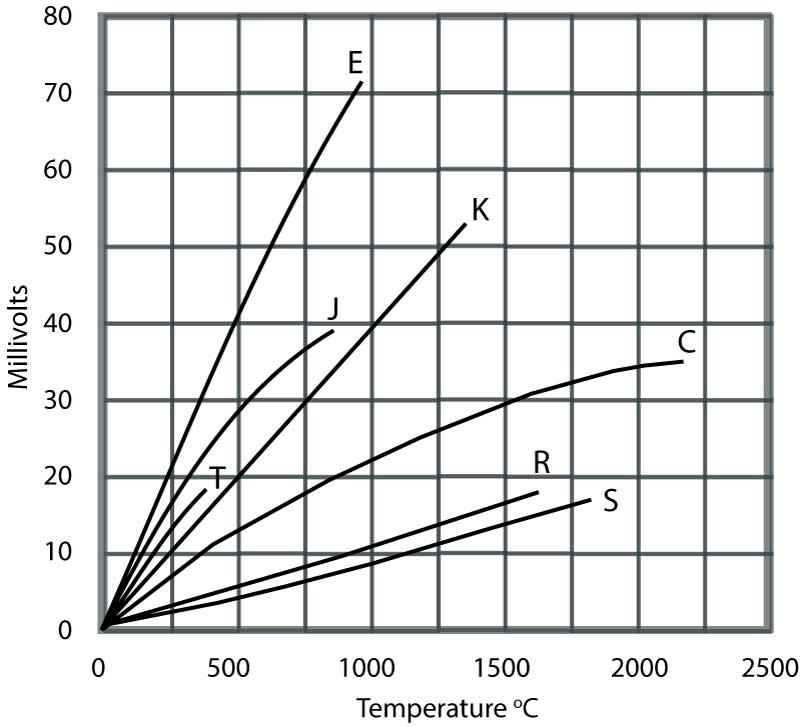
Figure 8 Thermocouple voltage/temperature characteristics
Thermocouples have the advantages of being robust, small (with an attendant fast response) and capable of measuring high temperatures. Their disadvantages include relatively low sensitivity and their need for cold junction compensation. Their response is non-linear, however for some restricted range applications the approximately linear output is acceptable. For more demanding applications linearisation methods must be employed.
Temperature Transducers
Thermocouple Circuits
Figure 9 shows an ambient-referenced measurement circuit (no cold junction compensation) employing an instrumentation amplifier, applied to measuring the temperature of a furnace. Such an arrangement is acceptable in applications where the ambient temperature variation can be neglected compared to the temperature being measured. For example a 15 degree variation from 25 degrees to 40 degrees is only 1% of a furnace temperature of 1500 degrees. Thus, in this application, neglecting cold junction compensation has a cost in terms of accuracy of 1%, which may be acceptable.Thermocouples are voltage sources of low source impedance (typically some 10's of ohms). This impedance, though low, is not insignificant, and so the thermocouple amplifier should have an input impedance high enough to avoid loading effects. The amplifier should also have low offset and offset drift.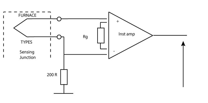
Figure 9
Thermocouple circuit for measuring furnace temperature
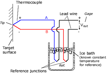 Figure 10
Using an ice bath to maintain a 0°C reference
The high temperature requires the use of a type S thermocouple which has a temperature coefficient of 5.9μV/°C; this gives an indication of the required offset drift specification from the amplifier. Suppose that the temperature has to be measured to within two percent; there has already been a one percent penalty due to the lack of cold junction compensation, thus inaccuracies due to offset drift must be kept within one percent. One percent of 1500 degrees is 15 degrees, corresponding to a thermocouple output of 88.5μV; thus an amplifier must be chosen with a total offset drift (due to temperature, time, power supply variations) which must be well within this figure.
If the ambient temperature of the reference junction causes an error that cannot be ignored then either the reference junction must be held at 0°C, as in Figure 10, or some electronic method must be devised for compensating for the difference between the reference temperature and zero. The former strategy is possible but not popular due to the need for an ice bath or its modem equivalent. The latter scheme is much more practical.
Figure 11 shows one implementation of an electronic cold junction compensation scheme, in which an AD590 integrated circuit temperature sensor measures the temperature of the reference junction above zero and subtracts a corresponding voltage from the measuring junction output, before it is amplified.
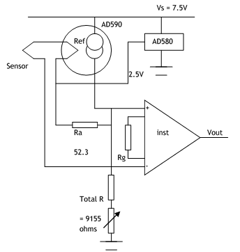
Figure 11
Cold junction compensation an AD590 temperature sensor
The basis of the compensation circuit is the AD590 temperature-controlled current source. This device, when positively voltage-biased, gives an output of 1μA/degree Kelvin. The AD590 is placed in thermal contact with the reference junction, and so supplies a current, Ia, equal in μA to the reference junction temperature in degrees Kelvin. For an ambient temperature of 25 °C, Ia=298.2μA.
The type J thermocouple used in this application has a temperature coefficient at the ambient temperature of 25 °C of 52.3μv/°C. Ra, which acts as a current to voltage converter, has its resistance value set at 52.3 ohms. The shunt resistor R in association with the regulated 2.5V source is designed to remove 273.2μA from Ia. The difference (here, (298.2-273.2μA = 25μA), in association with Ra produces a voltage equal to the voltage produced by the J couple for the temperature difference between ambient (here, 25°C) and 0°C.
Temperature Transducers
Resistance Varying Devices
The resistance of various conductors varies with temperature in a very predictable manner, and this principle is employed in an important class of temperature transducers. In this group are resistance temperature detectors (RTDs) and thermistors. These components are passive, which means that they need to have a signal applied to them to make them operate, and usually a bridge circuit is needed. This amplifies only the difference in temperature (the Differential) between the device and other bridge components, meaning that only the temperature reading is obtained, free from any noise or DC offsets.
RTD
RTDs usually comprise a wire sample of a known reference resistance at 0°C, packaged in a suitable manner. Platinum is probably the most commonly applied conductor, because of its purity, stability, repeatability and applicability at high temperatures. Thus a very popular transducer of this type is the PtRTD 100, which, as can be surmised from its designation, is a platinum RTD with a resistance at 0°C of 100Ω. These devices have the advantages of extreme stability with time and conformity to a standard curve (to within 0.02 °C). Their response is not perfectly linear but their non-linearity amounts only to a degree or two over spans of 100 °C; thus over restricted ranges they are frequently treated as linear devices.
In the range 0-100 °C, the resistance R of a PtRTD100 can be approximated:
R = 100 (1 + 0.0039T) where 0.0039 is the coefficient of resistance change with temperature in this range.
They can be used over the range -200 to +10000 °C with additional linearisation circuitry but are relatively expensive.
Fig 12 shows a simple interface circuit for an RTD. Here the resistance change is converted into a voltage change by driving a known current through the detector. The design is based on inexpensive op amps. Thus discrete transistors are needed to supply the relatively high value of excitation current that is needed to provide substantial output voltage amplitude.
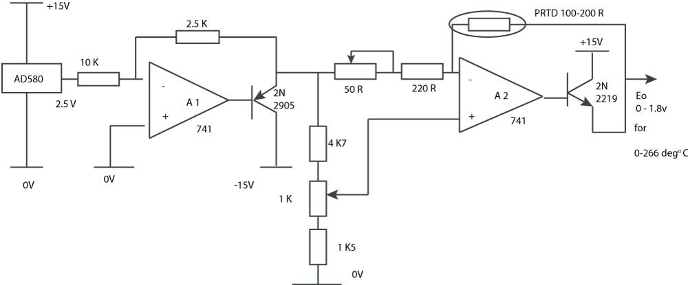
Figure 12 Interface circuit for a PTRD
Thermistor
Thermistors (thermally sensitive resistors) are circuit elements constructed from semiconductor material. They can be modeled electrically as temperature dependant resistors, usually with negative temperature coefficients (NTC). These temperature coefficients are high (about -4%/°C typically) and so large signal amplitudes are easily obtained from application circuits. Thermistors have the added advantages of being inexpensive and stable with certain types conforming to standard curves within 0.1°C.
They are much more sensitive than RTDs (i.e. their resistance/temperature coefficients are much larger) but have an exponential rather than a linear response so need linearisation circuits.
Thermistors are available in very small packages (tiny glass beads, for example) and this has advantages in applications where there is a very restricted access or where clearance between components is very limited. Small size also indicates a fast response, which is often desirable. The disadvantage of small size is that self heating can be a problem even at very low current excitation levels. A typical dissipation constant is 1mW/°C which means keeping self heating power levels well within 1 mW if measurements within one degree are required. Thermistors can be used over the range -100 to 400 °C.
Because Thermistors are semiconductor devices, their resistance at any temperature can be found from the simplified Steinhart-Hart Equation:
where T = Temperature in Kelvin
R = Resistance in Ohms
A, B, C = Steinhart-Hart coefficients often published by the thermistor manufacturer
Thermistor Circuits
Thermistors and RTDs are passive, that is, they have to have an excitation signal applied to them before an output can be obtained.
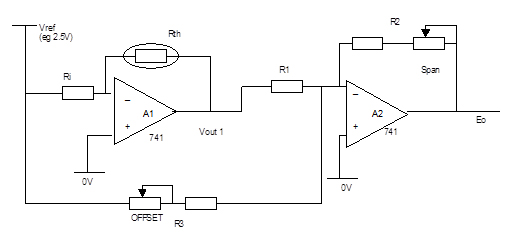
Figure 13 Thermistor interfacing Circuit
In Figure 13, Ri in association with Vref provides an excitation current which is supplied to the thermistor (resistance Rth) in the feedback loop of A1. Thus Vout1 is a negative voltage equal to the product of the constant current Vref/Ri and Rth (which of course is temperature-dependant). A2 inverts, scales and offsets Vout1 so that Vout2 describes a voltage proportional to the thermistor temperature, say 0-10 volts for temperatures of 0-100 °C.
In Figure 14 the thermistor is included in a potential divider which is part of a bridge. The bridge output is supplied to an instrumentation amplifier which rejects the common mode component while amplifying the temperature dependant differential component (by a gain set by the single resistor Rg) to provide the desired output voltage. Also important in this application is the high input impedance the instrumentation amplifier presents to the signal source. As the source has a relatively high impedance it should not be allowed to supply any appreciable current otherwise appreciable loading errors will occur.
As previously stated, thermistors are highly non-linear components, thus the output of the circuit as given in fig 13 is also non-linear. The non-linearity of circuit fig 14 is less pronounced as resistor Rg has a linearising effect. Improved linear operation is obtained in practice by the use of composite thermistor networks (available as commercial products) rather than single devices, and so improved versions of the given circuits are obtained by replacing the single devices within the dotted boxes with composites.
Figure 14(a) shows a two-terminal composite comprising two thermistors and two fixed resistors that can be used in the place of a single thermistor as in circuit fig 13; Figure 14(b) shows a three-terminal composite that can be used instead of a potential divider as in circuit Fig 14. In each case the individual thermistors and resistors are chosen to achieve linear resistance variation within specified limits over a given temperature range.
Find out more about thermistors at http://zone.ni.com/devzone/cda/tut/p/id/3643.
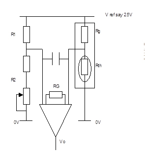
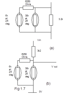
Figure 14 Thermistor Bridge Circuit
Time constant of temperature sensors
The temperature sensors covered above all have a first order response to a step change in temperature, i.e. if the ambient temperature is changed instantaneously, the sensor itself will take some time to reach the new value. Consider the specific case where a temperature sensor is moved from a cold water bath at temperature Tc to a hot water bath at temperature Th. To is the initial temperature of the sensor. You want to find the temperature of the sensor, T, as a function of time. Assume that the hot water, at temperature Th, will heat the sensor without appreciable cooling of the bath. The differential equation of interest becomes:
where C is the thermal capacity of the sensor and R is the thermal resistance of the sensor.
The thermal capacity is a function of the mass of the sensor and its heat transfer coefficient. The thermal resistance is a function of the surface area of the sensor and its specific heat. The solution to the differential equation is:
T(t) = (Th – Tc)[1 – e-t/] + T0
In the above equation, the value =RC is called the time constant and has units of seconds.
The system of heat transfer is analogous to a resistor and capacitor in series, where the capacitor is discharged through the resistor. In a transient heat transfer system, there is a resistance to temperature change and a certain capacity for heat that depends on the mass.
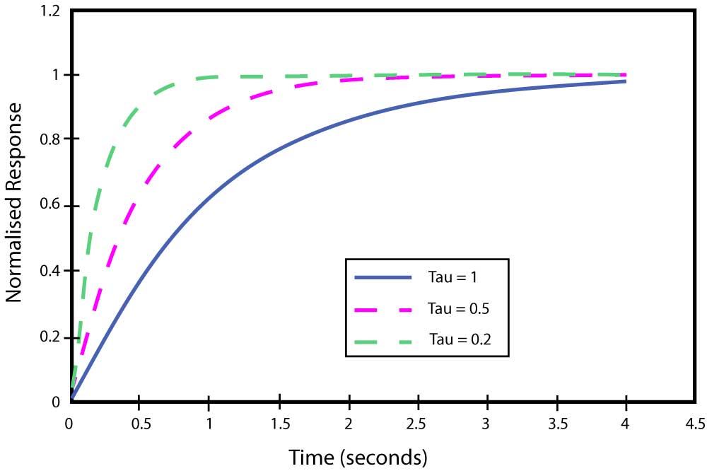
Figure 15 Exponential response to a step input for varying values of the time constant
The value of determines the “speed” of system response. The units for are seconds, and the smaller the value of , the sooner the value of e-t/ approaches zero, and the faster the response. When e-t/ approaches zero, the value on the right side of the equation approaches Th.
Task 3
A modern Engine Coolant Temperature (ECT) sensor is monitored by the engine computer to regulate various ignition, fuel and emission control functions, and to turn the radiator-cooling fan on and off. It needs to operate over the temperature range -120oC to +120oC. It can be powered by the car’s battery, but must be robust, reliable, cheap and accurate to within +2oC. It must be able to withstand corrosive spray (salt water), but does not need to be immersion proof. It must have response time of less than 5s to an input step change of 10o.
What sensor would you choose for this application and why?
The sensor which is most often used for this application is a thermistor because it is very reliable, easily protected against the harsh engine environment and cheap.
Summary
In this section you have learnt about some of the most common transducers used to measure displacement, speed and temperature. You have also seen some of the signal conditioning circuits used with these sensors to improve their performance.
References
Morris, Alan S. (2001) Measurement and Instrumentation Principles 3rd edition, Oxford: Butterworth-Heinemann (ISBN 0-7506-5081-8)
National Instruments Website http://www.ni.com/tutorials/ [21/06/17]
Sensorland Website http://www.sensorland.com/ [21/06/17]
Small Form Factors (2008) ‘Choosing a code wheel: A detailed look at how encoders work’ Journal of Modular Embedded Design PC(104)[online] [21/06/17]


